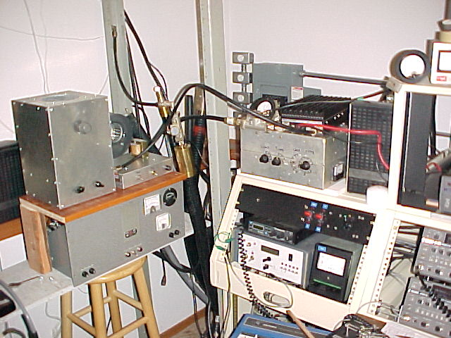
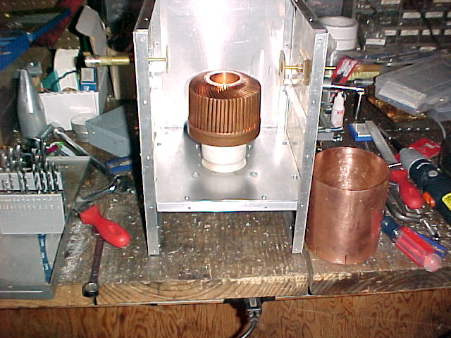
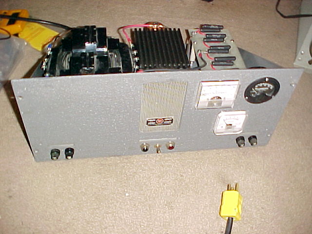
GS35B AMPLIFIER FOR 432 MHz built
by KL6M
POWER SUPPLY SCHEMATIC
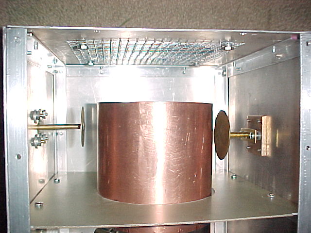
INPUT LINE DIMENSIONS
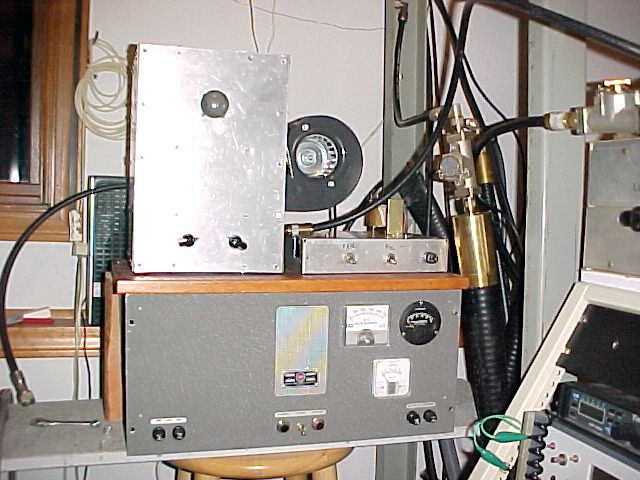
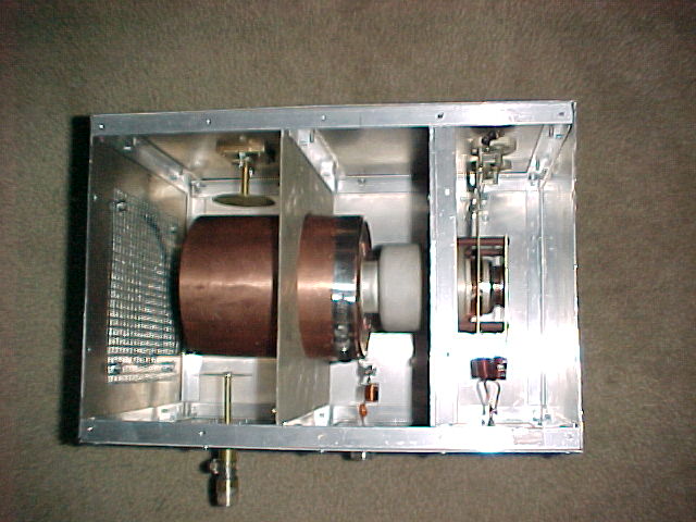
MORE PHOTOS (Added
20-July-2005)
Facts about the amp:
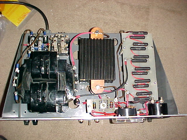
1. HV XFMR is rated 1450vac @ 1.8A. It delivers 4100vdc no load. The amp is capable of
about 1700 watts output with 100 watts drive.
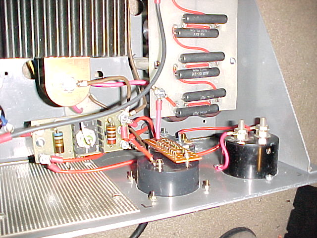
2. I am using a 30v Zener for bias and it results in idle current of between 175 and 275
mA. I plan to built an adjustable bias soon.
3. At 1500 watts output, the HV drops to about 3300v @ 850 mA, which is around 53%
efficiency. The grid current is off scale on my 100 mA meter, which I plan to replace with
a 200 mA meter.
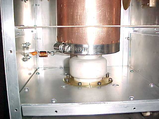
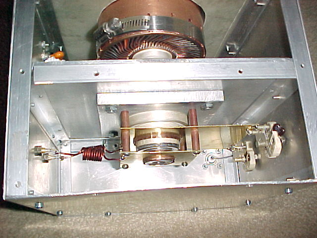
4. The input load control peaks up near the center while the input tuning is nearly all
the way to one side, so I plan to insert a low value capacitor in series to try to center
the adjustment.
5. I currently have no safety interlocks but I plan to build a control board with air flow
sensors, HV, filament, grid and other interlocks to preserve the GS35B in case of any
system failures.
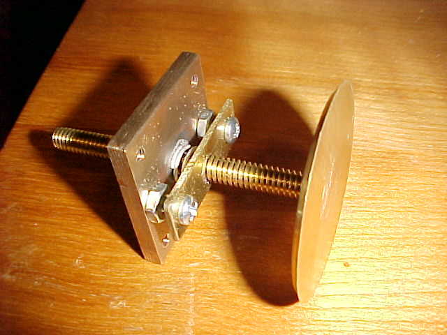
6. I am particularly fond of my output tuning disk tensioning device. It works very well,
although I am considering attaching a shield braid for more positive connection to ground.
7. Tuning is very smooth and once the output coupling is set, it does not require further
adjustment. The plate tuning, however seems to drift a bit with temperature, so I have
found myself adjusting it periodically.
8. Filament is running at 12.5vac @ 2.5A.
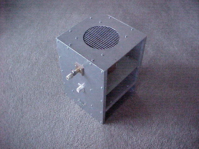
9. The input section gets very hot without cooling, but a small 60mm muffin fan cools it
very well.
10. My Idle current was too high so I have increased the bias. Since I am
using a very simple zener diode circuit for bias, I added series diodes to increase bias.
Currently I have about 38 volts bias which results in about 150 mA idle current.
11. I also added a shunt resistor to allow me to see my grid current. I
have not measured it yet, but I will revise this as soon as I do.